¶ OG Star TrackerlatitudeAdjustment
The device changes the polar axis height through the latitude arc plate, top/bottom knob holes and latitude adjustment lever. Before installing the camera load, the correct structure should be selected and locked.
¶ # Select latitude arc plate
- Standard arc plate: 25°–90°.
- Low latitude arc plate: 0°–25°. Use when the location latitude is lower than 25°.
¶ # Standard 25°–90° arc plate hole locations
| Target latitude | Knob hole location |
|---|---|
| 90°–60° | Top hole location |
| 60°–55° | Either top or bottom, choose the side with more appropriate adjustment margin |
| 55°–25° | Bottom hole position |
| Travel Mode | Must use top hole |
The original text of the instruction manual expresses the overlapping range: the top hole is used for about 90°–55°, the bottom hole is used for about 60°–25°, and 55°–60° can be used. The table organizes them into non-overlapping quick selection intervals.
¶ # Adjustment steps
- Remove or stabilize the camera load and loosen the latitude locking knob.
- Select the arc plate and hole position according to the location latitude.
- Turn the latitude adjustment knob to bring the polar axis close to the target height.
- Complete polar alignment with the azimuth adjustment.
- Tighten the latitude and the azimuth locking mechanism, and then start shooting after confirming that there is no looseness.
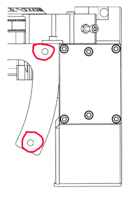
If the target latitude cannot be reached after adjusting to the end of the stroke, do not forcefully tighten it, but check whether the arc plate, hole position and installation direction are correct.